

6.1.1 Purpose of the chassis
There is a body and there are wheels (propellers, if in a scientific way). The question arises: how to connect the wheels to the car body, so that it is possible to drive a car, continuously transmit the traction from the engine to the drive wheels and at the same time comfortably overcome all the unevenness of the roads with various surfaces and without pavement? In this case, the connection of the wheels with the car body must be sufficiently rigid so that the car, while performing any maneuvers, simply does not turn over. The answer is simple - install the wheels on the intermediate link. A suspension performs a function of such a link.
Suspension elements should be as light as possible and provide maximum isolation from road noise. In addition, it should be mentioned that the suspension transmits the forces arising from the contact of the wheel with the road to the car body. Therefore, it is designed in such a way that it has increased strength and durability (see figure 6.1).
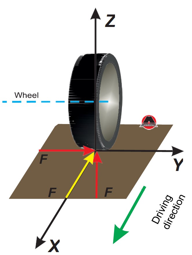 Figure 6.1 Forces on the wheel when it’s moving on the road.
Due to the high requirements for the suspension, each of its elements must be designed according to certain criteria, namely: the hinged joints used should easily rotate, but at the same time be sufficiently rigid and provide noise insulation for the car body; levers must transmit the forces arising from the operation of the suspension in all directions, as well as perceive the forces that arise during braking and acceleration; however, they should not be too heavy or expensive to manufacture.
 Figure 6.2 Dependent suspension.
 Figure 6.3 Independent suspension.
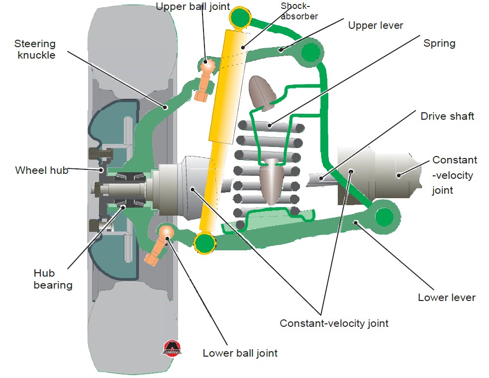 Figure 6.4 Example of spring suspension on two transverse levers.
 Figure6.5 Suspension with McPherson strut.
 Figure 6.6 Front suspension on two transverse levers with McPherson strut.
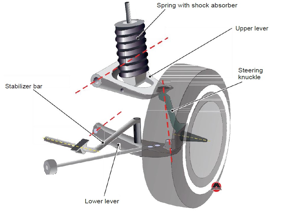 Figure 6.7 Layout of suspension of 1968 Ford Mustang.
 Figure 6.8 Example of rear semi dependent suspension.
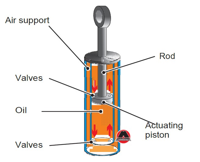 Figure 6.9 Double-tube telescopic shock absorber.
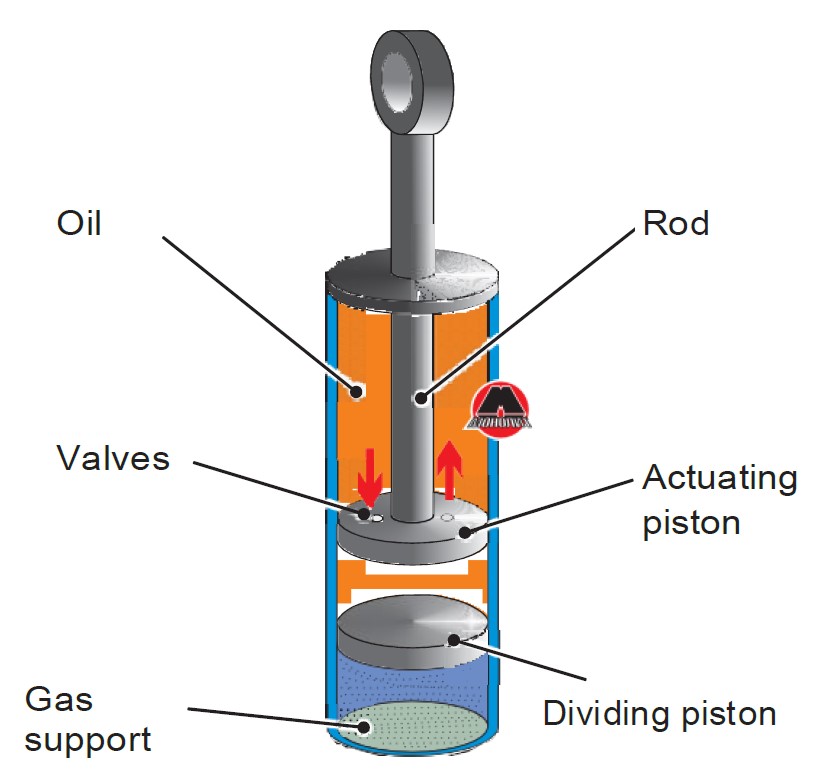 Figure 6.10 Single-tube gas-filled shock absorber.
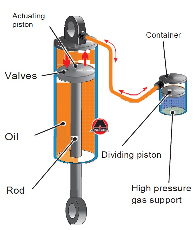 Figure 6.11 Single-tube gas-filled shock absorber, installed with rod upside down.


 Figure 6.16 Example of suspension with longitudinal torsion bar (long rod, which is fixed on the lever in front and on the car body cross-arm in rear).
 Figure 6.17 Air cushion.
 Figure 6.18 Front suspension with sub frame.
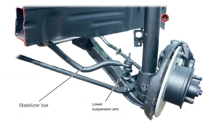 Figure 6.19 Example of stabilizer bar installation.


Our test questions are 100% compliant with the official ones, for which theoretical exams are taken in the service centers of Ukraine.
All other resources that claim that their test items are official, mislead you. The illustrations are modified and irrelevant text is placed in them. Preparing with the help of such resources, you can get confused on the official exam and simply do not pass it.