6.1.9 Suspension on two wishbones
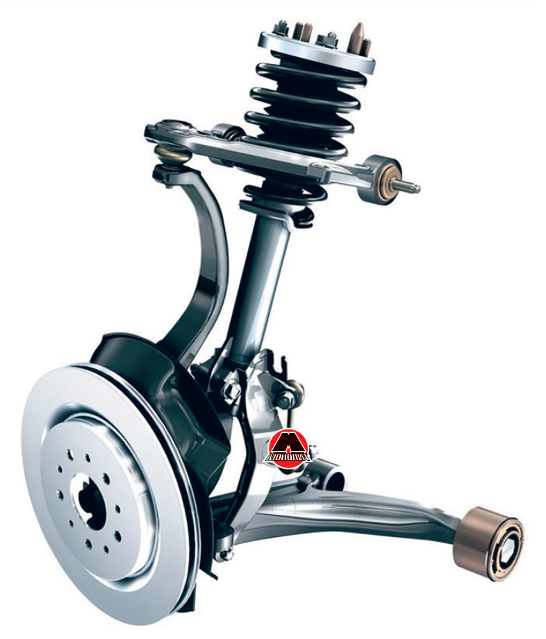
In order to get rid of "pecks", improve handling and increase energy intensity, one of the oldest suspension structures is used, which has come down to our times with significant transformations - a suspension on two wishbones (an example of which is shown in Figure 6.6).
 Figure 6.6 Front suspension on two transverse levers with McPherson strut.
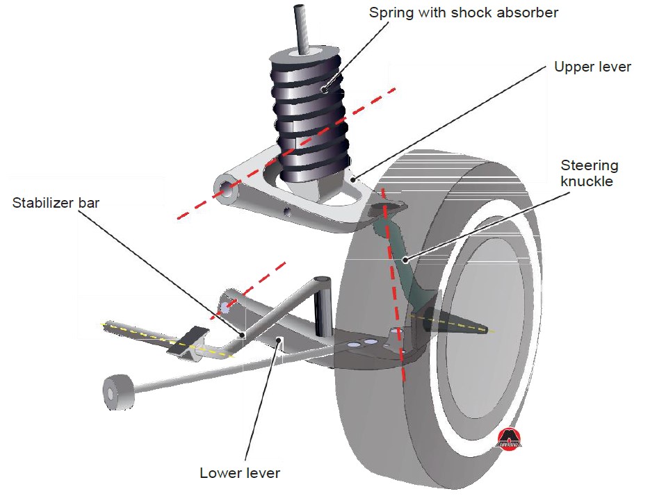
I this design there are a support lever (lower) and a guide lever (upper) that are attached to the steering knuckle. The lower part of the shock absorber is installed on the support arm, or a separate spring and a separate shock absorber. The upper lever serves as a direction of the wheel movement in the vertical plane, minimizing its deviation from the vertical. The way the levers are positioned relative to each other has a direct impact on the behavior of the car while it is moving. Pay attention to Figure 6.6. Here the upper lever is maximally retracted from the lower lever upwards. It was necessary to lengthen the steering knuckle in order to reduce the impact of forces on the car body during suspension operation. In addition, this lever is installed at a certain angle to the horizontal axis of the vehicle in order to avoid the notorious "pecks". The essence remains the same, but the appearance, geometric and kinematic parameters change.
Note
There is still one very significant drawback in this design despite all the advantages. This is the deviation of the wheel from the vertical axis during suspension operation. There seems to be a solution - lengthening the levers. This is good in case if the car is frame-based. But in case if the body is load-bearing, then there is nowhere to lengthen - further is the engine compartment. Thus manufacturers approach the solution in a non-standard way: they try to make the lower lever as long as possible, and the upper one - set as far as possible from the lower one.
Note
It should be mentioned that in case if the spring and shock absorber or McPherson strut are attached with their lower end to the upper lever (as in the case shown in Figure 6.7), it is the upper lever that becomes the support lever, while the lower one goes into the category of guides.
 Figure 6.7 Layout of suspension of 1968 Ford Mustang.


2 MB