4.4.8 Operating procedure
The order of the engine cylinders. In case if there are more than two cylinders in the engine, then for a more uniform and balanced operation of the unit, it is necessary that the working stroke in each of the cylinders is implemented not simultaneously, but in a certain sequence. While this sequence shall be mainly determined by the number of cylinders.
Note
For ICE with the same number of cylinders, there can be several options of the order of the engine cylinders.
So, for example, the most common order of the engine cylinders for a four-cylinder engine is: 1 - 3 - 4 - 2. Such a record suggests that first the working stroke will be made by the piston of the first cylinder, then the third, fourth and second, respectively. As an example, we will describe the operation of a four-cylinder inline engine.
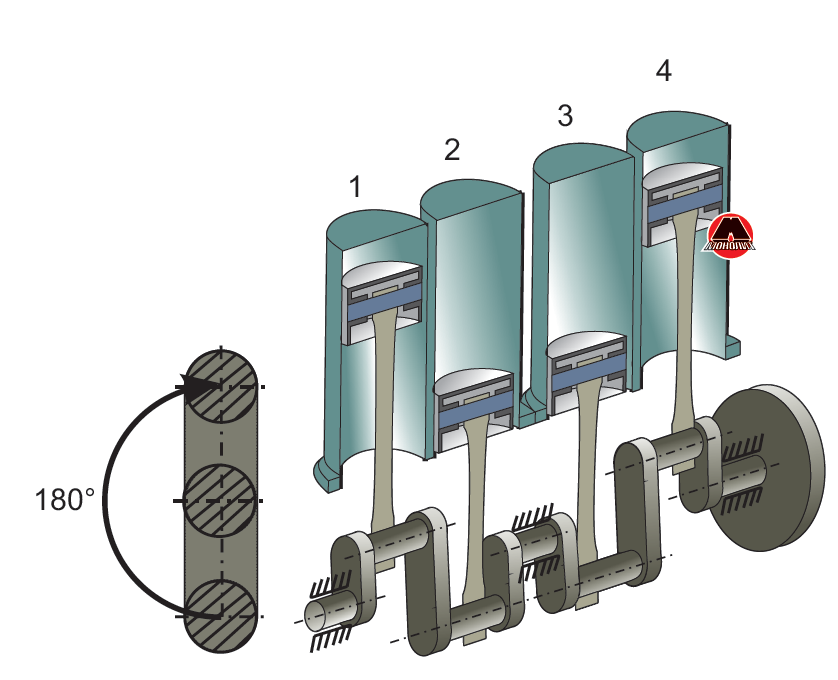 Figure 4.6 Schematic diagram of four-stroke, four cylinder in-line engine.
In a four-stroke, four cylinder in-line engine (shown in Figure 4.6), the crankshaft cranks are located in the same plane: two extreme cranks, 1st and 4th, at an angle of 180 ° to the two middle cranks - 2nd and 3rd. When the shaft rotates, the pistons of the first and fourth, as well as the second and third cylinders move in pairs in the same direction. When the pistons of the first and fourth cylinders come to TDC, the pistons of the second and third cylinders are in BDC, and vice versa. In each of the cylinders, the working cycle is completed in two revolutions of the crankshaft, and the alternation of strokes is selected in such a way that different strokes occur simultaneously in all cylinders. This ensures uniform rotation of the shaft. Let’s suppose that during the first half-turn of the shaft (from 0 ° to 180 °) in the first cylinder, the piston goes from TDC to BDC, and a working stroke occurs in it. Then, in the fourth cylinder, the piston also moves to the BDC, but the fuel mixture is injected. In the second and third cylinders, the pistons move to TDC, while the working mixture is compressed in the third cylinder, and exhaust gases are released in the second.
Note
The valve opening and closing moments are controlled by the camshaft (described in more detail below).
During the next three half-revolutions of the crankshaft the strokes in each of the cylinders will follow in the usual sequence for a four-stroke process.
By the time the shaft finishes the fourth half-turn, all the strokes of the working cycle have occurred in all cylinders. With further rotation of the shaft, the strokes will be repeated in the same sequence.
When a four-stroke four-cylinder engine is operating, there is one working stroke for each half-turn of the crankshaft, and the working strokes alternate not in the order of the cylinders, but in a different sequence. Firstly, the working stroke takes place in the first cylinder, then in the third, then in the fourth and, finally, in the second, that is, the working strokes alternate in the following order: 1 - 3 - 4 - 2.This order of alternating cylinder strokes is called the engine operating procedure.
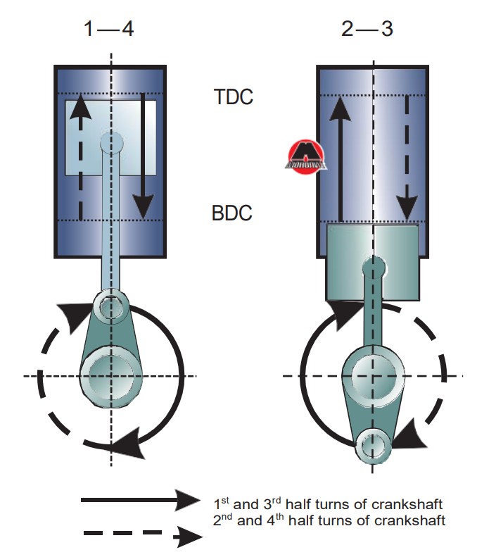
Figure 4.7 Half turns of crankshaft.
With the same form of arrangement of the cranks of the shaft, but with a different order of opening and closing the valves, which depends on the design of the gas distribution mechanism, the four-cylinder engine may have a different sequence of alternating strokes and a different order of operation. In case if during the first half-turn of the shaft in the third cylinder there will be an exhaust stroke, and in the second - a compression stroke, then the alternation of strokes in the engine will change, and an operating order will be obtained: 1-2-4-3.
| Half turns of crankshaft
|
Angles of rotation of the crankshaft, °
|
Cylinders
|
|||
| 1 st
|
2 nd
|
3 rd
|
4 th
|
||
| 1 st
|
0 – 180 | Working stroke
|
Exhaust
|
Compression
|
Intake
|
| 2 nd
|
180 – 360 | Exhaust
|
Intake
|
Working stroke
|
Compression
|
| 3 rd
|
360 – 540 | Intake
|
Compression
|
Exhaust
|
Working stroke
|
| 4 th
|
540 – 720 | Compression
|
Working stroke
|
Intake
|
Exhaust
|








2 MB